Inventor :- Curt St. Hilaire (StudGuard)
Author :- Siddhant Rane
Status :- Filed
Abstract:- The invention disclosed herein relates to a water and mold resistant wall installation system that includes a base plate which is drilled to the ground using nails. The baseplate comprises of a plurality of slots for clogged water passage. A plurality of holders are mounted at a uniform inter-space on top the base plate. Wall studs are covered in a protective sleeve and are inserted into the holders for upright alignment. The base plate comprises of an extended lip in its horizontal plane which mounts the dry wall and keeps it above ground level, protecting it from water and slab moisture absorption. The base plate, holders and the protective sleeve are made up of a water and mold resistant composite material.
Background :- Conventional residential construction typically involves the use of wall studs and dry
wall. A spruce wooden base plate is anchored to the ground forming a base mount for the wall studs. A dry wall is constructed on the wall studs and forms a typical wall assembly. In case of a water leak or
flooding, the wall assembly absorbs water. Concrete slab moisture can be absorbed in the dry wall and
cause excessive damage initiating at the dry wall base. This is termed as ‘water damage’. Water damage
takes long weeks of restoration procedures that involve the use of commercial fans and heat to dry the
water-soaked areas. Other than the time consumed to recover from water damage, the durability of the
wall assembly is negatively affected. Because the traditional base plate is of an organic material,
moisture is retained even after restoration. This situation creates the ideal environment for rapid mold
development. Restoration of the partial wall assembly after moisture and water absorption is very
expensive. The current invention provides an advantageous solution through the use of water and mold
resistant materials. This enhanced system also facilitates a more efficient wall installation procedure
whereby providing pre-drilled slots for the wall stud holders centered at required standards which are a
perfect fit for batt insulation.
Detailed Description:- The following detailed description is of the best currently contemplated models
of the invention. The description is not to be taken in a limiting sense, but is made merely for the
purpose of illustrating the general principles of the invention. The scope of the invention is best defined
by appended claims.
In the drawings:
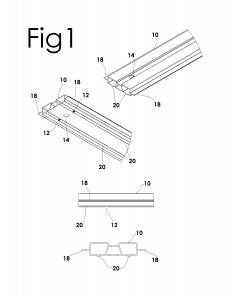
Fig 1 represents a three-dimensional isometric view of the top and bottom, a front and side
orthographic view of the base plate.
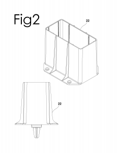
Fig 2 represents a three-dimensional isometric view and a side orthographic view of the holder.
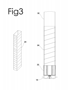
Fig 3 represents a three-dimensional isometric view and a side functional view of the protective sleeve.
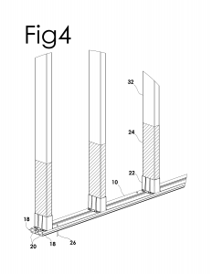
Fig 4 represents a three-dimensional isometric view of the assembled system.
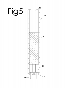
Fig 5 represents a front orthographic view of the assembled system.
The present invention is a prefabricated wall installation system that provides water and mold
resistance to internals of the wall, dry walls and wall studs. The system is collectively defined by an
assembly of a base plate, a holder and a protective sleeve. The three parts are assembled to
collectively embody a system that provides extensive water and mold resistance to the
affixed dry wall and wall studs which are an integral part of the system. The embodiment of this
invention is suited for use in both commercial and residential construction.
Referring to Fig 1-5, the baseplate 10 is the first part of the system. The baseplate 10 has a top, a bottom, two opposite sides, an outer side and an inner side. The baseplate 10 is anchored to the ground using nails 26 drilled at a uniform inter-space. The baseplate 10 is an elongated hollow strip of water and mold resistant composite material, preferably of a quadrilateral cross section that runs parallel to the wall. The top face of this part has locating points 14 which are round holes to install the holder 22. These locating points 14 are fabricated at a uniform inter-space depending on regional standards and preferences. The two opposite sides have a ‘lip’ 18 that extends in a horizontal plane. These lips 18 are extended rims protruding away from the body to form a platform to dispose and elevate a dry wall 34 above the ground level. The bottom face of the baseplate 10 has at least two identical tracks 20 protruding at the outer side into the ground when anchored. The tracks 20 conceal the baseplate flat against the ground. The tracks 20 run parallel along the baseplate’s 10 length. At a uniform interval, the tracks 20 break apart along the length to form apertures that have small holes for clogged water passage called ‘slots’ 12 which open to the ground. In fabrication, the slots 12 are drilled at a uniform inter-space inside the tracks 20 in the baseplate 10. The inner side of the baseplate 10 forms a hollow channel that drains clogged water through these slots 12 into the ground.
The holder 22 is a water and mold resistant composite material body having a bottom locating tab 16, a mount section and a top container body with a hollow cavity preferably fabricated to truncated square pyramid shape. The locating tab 16 on the holder 22 coincidentally fits the locating points 14 on the base plate 10 . The holder 22 is mounted onto the baseplate 10 such that the hollow cavity of the container body faces the top. A plurality of screws or nails are used to secure the holder 22 onto the base plate 10. The mount section on the holder 22 has pre-drilled holes through which the screws or nails are drilled from holder 22 into baseplate 10. The top container body of the holder 22 has a hollow cavity that is dimensioned and fabricated to contain a wall stud 32 along the cross-sectional area, mounting the wall stud 32 vertically upright when disposed inside the holder 22. A plurality of holders 22 are inter-spaced uniformly parallel on the baseplate 10 to form multiple mount points for the wall studs 32.
The protective sleeve 24 wraps the wall stud 32 before mounting inside the holder 22. The protective sleeve 24 is a thin, flexible, formable water and mold resistant piece of composite material having a first open end and a second closed end taking a tube shape. The protective sleeve 24 is slid onto the wall stud 32 from bottom to top, the second closed end of the protective sleeve 24 covers the base of the wall stud 32 when disposed upright inside the holder. The top first open end draped up on the wall stud 32 and covers the wall stud 32 from bottom to at least halfway or more depending on the size and application.
Method of Installing the Prefabricated Water and Mold Resistant Wall Installation System
According to Embodiment of the Present Invention
The base plate 10 is disposed flat on the ground and anchored with nails 26 that penetrate through the base plate 10 into the concrete slab. The base plate 10 is sealed flat against the concrete slab. The holder is mounted on top of the base plate 10 wherein the locating tabs on the holder 22 base coincidentally align with the locating points 14 on the base plate 10. The holder 22 locks onto the base plate 10 with a set of screws or nails that mount the holder 22 upright. A plurality of holders 22 are mounted at a uniform inter-space onto the baseplate 10 forming a base assembly. The protective sleeve 24 is wrapped on the wall stud 32 wherein the bottom end of the wall stud 32 is covered with the second closed end of the protective sleeve 24. The wall stud 32 comfortably slides into the protective sleeve 24. The first open end of the protective sleeve 24 is draped up on the wall stud 32. The protective sleeve 24 covers at least half of the wall stud’s 32 height starting from the bottom end. The protective sleeve 24 covered wall stud 32 is constructed inside the holder 22. A plurality of protective sleeve 24 covered wall studs 32 constructed inside the respective holders 22 onto the base assembly collectively form the internal wall assembly. A sheet of drywall 34 is mounted vertically on the lip 18 of the base plate 10 and constructed along the wall studs 32. The bottom edge of the dry wall 34 is disposed onto the lip 18. The lip 18 elevates the dry wall 34 from bottom. The dry wall 34 is upheld at least half inch above the ground level. The lip 18 functions as a partition between the drywall 34 and the concrete slab or the ground.
The system can be assembled in variant sequences, such that the protective sleeve 24 can be first wrapped onto the wall stud 32, then inserted into the holder 22, and finally mounted onto the anchored base plate 10 and secured using screws or nails. The parts of this system can be employed for variant applications and can be used either in conjunction with other parts or by themselves.
Advantages of the Present Invention over Conventional Methods
Water leaks and flooding can be caused from natural factors being rain, snow or intruding tree roots, or
domestic factors being broken seals, clogged lines, corrosion, damaged pipe joints, excessive water
pressure, loose connectors or rapid temperature changes. Considering a scenario of water leakage
inside a structural unit constructed with the method disclosed in the current embodiment of the
invention, the leak could be either on the internal or external side of the wall assembly. In an event
wherein the leak is at the internal side of the wall assembly, the leaked water is likely to drip down onto
the base plate 10. The leaked water then flows under the base plate 10 through the apertures fabricated
between the tracks 20 onto the concrete slab or ground. If the leaked water drips inside the holder 22, the wall stud’s 32 bottom secured with the protective sleeve 24 and prevents the wall stud from absorbing water. The leaked water then flows inside the base plate 10 through the holder 22 and is channeled out through the slots 12 onto the concrete slab or ground. The assembly prevents water clogging or water absorption at the internal side. In an event wherein the leak is at the external side of the wall assembly, the leaked water is likely to puddle onto the floor. Excessive leaking leads to flood. The flooded water is near the corners of the wall assembly flows under the base plate 10 through the apertures between the tracks 20 and seeps onto the concrete slab or ground. The lip 18 elevates and prevents the dry wall 34 from absorbing water. The assembly prevents flooding and water absorption at the external side. The base plate 10 is fabricated with pre-drilled locating points 14 as mount points for the locating tabs on holder 22. These locating points 14 are measured and spaced depending on general geographic and territorial standards. The assembly further benefits by reducing evaluation time and providing an accurate and efficient wall installation system.
Claims:
The embodiments of the invention in which an exclusive property or privilege is claimed are defined as follows:
-
A prefabricated wall installation system for water and mold resistance comprising:
a base plate fabricated of water and mold resistant composite material, the said base plate having a top face, a bottom face and two opposite sides, an inner side and an outer side, fabricated to form an elongated hollow strip, the said base plate having locating points at uniform intervals on the top face, the said opposite sides of the said base plate having lips in the horizontal plane, the bottom face of the said base plate having at least two parallel tracks that split along the length at uniform interval to have apertures that possess slots, the said base plate having a hollow channel at the inner side;
at least one holder, the said holder fabricated of water and mold resistant composite material, the said holder having a top container body with a hollow cavity, a locating tab and a mount section , the said locating tab fabricated at the bottom coincidentally fitting the said locating points on the said base plate, the said holder wherein the said hollow cavity being dimensioned and fabricated to match the cross sectional area of a wall stud, the said holder having a mount section with pre-drilled holes to mount onto the said base plate;
at least one protective sleeve, the said protective sleeve fabricated of water and mold resistant composite material, the said protective sleeve having a thin, flexible, formable, tube shape with a first open end and a second closed end forming an enclosure, the said protective sleeve dimensioned and fabricated to contain a wall stud.
-
A prefabricated wall installation system of claim 1 wherein the said baseplate being anchored to the ground using nails, the said tracks on the baseplate being concealed flat against the ground and the said slots inside the tracks open into the ground.
-
A prefabricated wall installation system of claim 1 wherein the said locating tabs on the holder coincidentally fit into the locating points on the baseplate and a plurality of screws or nails being employed to mount and secure the holder onto the baseplate.
-
A prefabricated wall installation system of claim 1 wherein the said protective sleeve being slid onto the wall stud such that the said second closed end covers the bottom end of the wall stud and the said first open end being pulled up covering the wall stud from bottom to more than half the height of the wall stud disposed vertically upright
-
A prefabricated wall installation system according to claim 2, 3 and 4 wherein the said wall stud covered with the said protective sleeve being disposed inside the holder such that the bottom end of the wall stud covered by the second closed end of the protective sleeve being inserted into the said hollow cavity of the holder, disposing the wall stud vertically upright into the holder onto the baseplate.
-
A prefabricated wall installation system of claim 5 wherein a plurality of the said protective sleeve covered wall studs inserted into a plurality of said holders mounted onto the said base plate.
-
A prefabricated wall installation system of claim 1 wherein a dry wall being disposed onto the said lip of the baseplate such that the bottom edge of the dry wall being mounted on the lip of the base plate, elevating the drywall above the ground level and the lip being a partition between the dry wall and the ground.
-
A prefabricated wall installation system according to claim 6 and claim 7 wherein the said drywall being disposed onto the lip of the baseplate and constructed along the said wall studs.
