Author / Inventor :- Siddhant Rane (Kizis System)
Status :- Filed
Abstract:- Invention disclosed herein pertains to a wall installation system, typically for outdoor or
partially indoor applications, that employ two ‘[‘ shaped brackets that interlock together to form a
frame that contains a main panel. The main panel integrates a heating or cooling mechanism powered
by electricity and a thermoelectric module. The main panel is disposed inside the frame forming a single
assembly. A plurality of such assemblies constructed serially interlock together to collectively embody a
wall installation system. The main panel can be easily interchanged without deconstructing the
assembly. The entire system is fabricated of thermal insulated water and mold resistant composite
material.
Background: – Conventional residential and commercial applications typically employ organic or metallic
materials for outdoor decking and fencing in backyards, patios, porches, balconies etc. Most widely used
materials involve wood, glass and steel. Organic materials like wood absorb water, which causes mold to
form and adversely affects the life and quality of the fence. This involves procurement measures and
adds up the maintenance. Glass and steel applications are costly and do not ensure optimum thermal
insulation. The overall adoption of these materials is limited and involves costly maintenance. Space
heaters and coolers are readily available in the market that come in variant specifications and can be
adopted depending on the application. In cold countries, these heaters are put to work depending on
the necessity whereas in warmer countries, space coolers or cool air conditioners are used. In most
outdoor applications viz. restaurant patios, outdoor coffee shops, gas stations, house backyards,
balconies etc., a structure of organic or metallic materials is constructed to ensure minimal heat loss. A
space heater is used in conjunction with the construction to provide a comfortable experience at
preferably desired temperatures. This structure is usually expensive to construct and deconstruct, and
the used materials might not qualify for reuse. The heaters that work on convection principles usually
take a lot of time to heat the space, especially in snowy icy climate and are expensive to operate. The
radiant heaters need to be placed directly in front of objects to be heated up. The experience can be
limited depending on the number of heaters being used. The operating costs for electric heaters are
expensive and require extension outlets while the gas operated heaters are expensive to refill. These
heaters take up space and a contact with the hot surfaces could sometimes prove fatal. In warmer
places, an air conditioner is used to regulate the temperature. The air conditioners are expensive to buy
and operate and require thermal insulation in order to function efficiently which constraints the
application only for indoor purposes. Most outdoor coolers require cold water or ice as temperature
regulator and the experience is limited to the number of coolers being used.
The present invention is an easy to construct, piece to piece interlocking wall installation system
that integrates an interchangeable panel. The panel contains a heating or cooling mechanism which is
powered by electricity and utilizes thermoelectric affect as a backup power supply in the heating
application and as the cooling element in the cooling application. The system easy to construct-
deconstruct and is reusable. The panel can be interchanged depending on the weather without taking
apart the entire assembly. The system being fabricated of thermal insulated, water and mold resistant
composite material makes it efficient, low cost, non-toxic and recyclable.
Description:- :- The following detailed description is of the best currently contemplated models
of the invention. The description is not to be taken in a limiting sense, but is made merely for the
purpose of illustrating the general principles of the invention. The scope of the invention is best defined
by appended claims.
In the drawings:
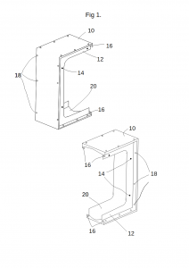
Fig 1. represents a three-dimensional isometric view of the bracket.
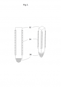
Fig 2. represents a side orthographic view and a three-dimensional view of the post.
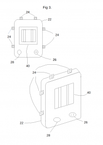
Fig 3. represents a front orthographic view and a three-dimensional view of the heating system integrated
main panel.
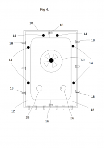
Fig 4. represents a front orthographic view of the cooling system integrated main panel disposed in a
constructed frame.
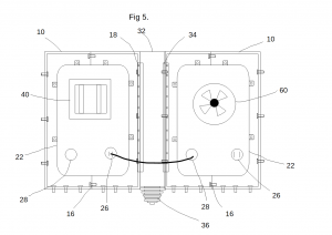
Fig 5. represents a front orthographic view of an assembly with two frames constructed along a post with
disposed main panels each integrated with a heating and cooling system respectively.
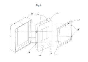
Fig 6. represents a three-dimensional view of the disassembly of themain panel from a constructed frame.
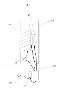
Fig 7. represents a side orthographic view of the internal cooling assembly contained inside the main
panel.
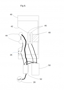
Fig8. represents a side orthographic view of the internal heating assembly contained inside the main
panel.
The terms “interior” and “exterior” in the following description are relative to the observer’s point of view
such that the term “interior” is referred to the area enclosed inside a fully constructed embodiment of the
present invention, also the area towards which the heating and cooling system functionalities are to be
employed. The “exterior” is referred to as the area excluded outside a fully constructed embodiment of
the present invention, also the area where the heating and cooling system functionalities are not be
employed. The terms “inner” and “outer” are used in relation to the present embodiment of the main
panel such that the term “inner” refers to the inside of the main panel enclosed between all the surfaces
of the main panel and “outer” refers to the outside of the main panel not enclosed between all the
surfaces of the main panel. The term “fastening mechanism” refers all characters of materials used for
fastening or connecting parts like screws, nut and bolts, visors, self-tapping clips etc.
The present invention is a prefabricated wall installation system that integrates a temperature regulating
mechanism powered primarily by AC electricity. The heating mechanism utilizes a heater with a
thermoelectric module to generate backup electricity used simultaneously in conjunction with AC
electricity. The cooling mechanism utilizes the thermoelectric module to regulate the temperature using
AC electricity and solar panels. The present embodiment of the invention involves four major parts viz. a
frame, a post, a main panel and an internal assembly. The main panel houses the internal assembly and
can adopt alternative embodiments disclosed herein. The invention also comprises of formable thermal
insulated water and mold resistant gaskets to fit various connecting parts of the embodiment.
According to Fig1. – Fig 8, the frame being the first part of the system comprises of a ‘[‘ shape bracket
10. The bracket 10 has a base, a side and a top, each joined together at ends to form a ‘[’ shape. The
present embodiment of the bracket 10 possesses a quadrilateral shaped cross-sectional area. The
horizontal part along the bottom surface is referred to as base. The horizontal part opposite to the base,
away from the bottom surface is referred to as the top. The vertical part connecting one end of the base
and the top is referred to as the side. The open non-connecting area of the bracket 10 is referred to as
the mouth. The base is a flat ledge which seals against the surface below. The base possesses pre-drilled
holes at uniform interval at both interior and exterior to employ fastening mechanism to anchor and
secure the bracket 10 to the ground or surface below. The side is a vertical ledge of the frame
connected to the base at lower end and the top at the upper end. The top has similar dimension and
aesthetics as the base but fabricated to the frame in an upside-down inversely manner from the base.
The base, side and top collectively form a channel at the inner edge hereby referred as cavity 20. The
cavity 20 beings at the mouth near the top and ends at the mouth near the base forming a channel with
a slightly curved surface. The base and top possess a hinging mechanism at the mouth referred as the
primary connector 16. These primary connectors 16 possess holes to mount and secure one bracket 10
against another using a set of fastening mechanisms. The bracket 10 possesses a set of hinging
mechanism referred as secondary connectors 18 along the side which employ fastening mechanisms to
connect the frame to a side wall, a post 32 or to another frame. A mid-sectional area along the interior is
detachably connected to the bracket 10 with a set of screws. This part is referred as the cap 12 and can
be detached to replace the main panel 22 from the assembly to without unmounting the entire
assembly. The cap 12 screws onto of a plurality of mounting points 14 on the bracket 10 that
coincidentally match with the mounting parts 24 of the main panel 22 to dispose and attach the main
panel 22 in position. The cap 12 is the interior face of the bracket wherein the primary connectors 16
form an integral part of the cap 12, excluding the secondary connectors 18 or the pre-drilled holes at the
base and the top. The rear side of the cap 12 possesses a curved shaped surface which also partially
forms the cavity 20. A plurality of screws engages two brackets 10 connected at the mouth through the
primary connectors 16 collectively forms a frame. The frame encases a quadrilateral shaped cavity 20 to
dispose the main panel 22. The bracket 10 is fabricated of thermal insulated, water and mold resistant
composite material.
The post 32 being the second part of the system acts as a connector for two frames. The post 32
embodies a quadrilateral cross-sectional area with an elongated top body and a conical pine shaped
base 36. The corner edges of the post 32 possess connectors 34 similar to the secondary connectors 18
of the bracket. Both the post’s connectors 34 and bracket’s secondary connectors 18 coincidentally
match to employ a set of fastening mechanism to connect the two parts together. The height and width
of the post 32 matches the height and width of the bracket. The conical pine shaped base 36 of the post
32 aids in anchoring and erecting the post 32 on uneven and soft surfaces. An anchored post 32 when
connected between two frames ensures strength and stability to the assembly. The post 32 is fabricated
of thermal insulated water and mold resistant composite material.
The present embodiment of the main panel 22 possesses two quadrilateral shaped plates connected in
fabrication with a rounded curved edge along the perimeter. The hollow area between the panel 22
houses the internal assembly. The main panel 22 has a top that aligns with the top of the frame, a
bottom that aligns with the base of the frame, two opposite sides that align with the sides of the frame,
an inner that houses the internal assembly, an outer, an interior and an exterior. The rounded curved
edge of the main panel 22 coincidentally matches the curve of the cavity 20 on the frame. The main
panel 22 is comfortably contained inside the frame. The main panel 22 possess a plurality of mounting
parts 24 along the rounded curved edge fabricated at the top and the sides of the main panel 22. These
mounting parts 24 are protrusions with a hinging mechanism that coincidentally match the mounting
points 14 on the cap 12 of the brackets 10. These mounting parts 24 employ a set of fastening
mechanism to attach the main panel 22 to the frame. The internal assembly forms an integral part of
the main panel 22 as all the components of the internal assembly are contained inside the main panel
22.
A gasket is the secondary part of the system fabricated of a formable thermal insulated water and mold
resistant composite material. The gaskets act as a seal between the connecting parts to ensure optimal
thermal insulation. The gaskets also prevent wear and tear of parts due to surface friction. The gaskets
are fabricated to variant shape and sizes to fit all connecting parts.
Embodiment and Working of the Internal Assembly with Heating Panels
The internal assembly comprises of a heating assembly 40, a thermoelectric module 46, a
supercapacitor- battery hybrid 50, plurality of heat sinks, an exhaust fan 48, a programmable charge and
discharge electric module 52, a lid protected power outlet 26. The heating assembly 40 considered in
the present embodiment specifically uses a radiant infrared heater. The heating assembly is contained
inside the main panel 22 such that the surface of the main panel 22 at the interior displays and regulates
the use of heating assembly 40 towards the interior. A heating element 44 is contained in a heat and
corrosion resistant tube, like ceramic or quartz. A infrared transparent heat and corrosion resistant
material covers the heating element 44 at the interior to avoid direct contact. This heating element 44
emits infrared rays that provide radiant heating. A curved reflective plate 42 of heat and light reflecting
material like aluminum is used to direct the infrared light towards the interior side. The reflective plate
42 attaches to the main panel 22 with a layer of thermal insulation between the main panel 22 and the
reflective plate 42 to avoid heat transfer to the main panel 22. The rear side of the reflective plate 42
directly connects to a set of heatsinks that are thermally pasted onto the hot plate of a thermoelectric
module 46. Another set of heat sinks are thermally pasted on the cold side of the thermoelectric module
46 along with an exhaust fan, disposed at the exterior side. The thermoelectric module’s 46 output
wiring connects to the supercapacitor battery hybrid 50. The input junction of a programmable charge-
discharge electric module 52 connects to the supercapacitor battery hybrid 50 . The input junction of
the programmable electric module also connects AC electric input 28. As the heating assembly 40 is
powered with AC electricity 28 through the output junction of the programmable electric module, the
reflective plate 42 reflects the infrared rays from the heating tubes 44 towards the interior side. The
reflective plate 42 absorbs some amount of heat which is considered heat loss. This absorbed heat rises
the temperature of the reflective plate 42 that is connected to the heatsinks on the hot side of the
thermoelectric module 46. Through convection, the temperature at the hot side of the thermoelectric
module 46 rises. The cold side of the thermoelectric module 46 is disposed at the outer surface of the
main panel 22 at the exterior in the cold climate and the low temperature is maintained using heatsinks
and exhaust fan 48. This temperature gradient between the hot and cold sides of the thermoelectric
module 46 will result in power generation which is stored to the supercapacitor-battery hybrid 50. The
programmable charge discharge electric module 52 switches the power source from AC electricity 28 to
supercapacitor-battery hybrid when sufficient energy is collected in the supercapacitor-battery hybrid
50 to power the heating assembly 40. The programmable electric module 52 also connected to a power
outlet 26 that is protected with a lid. Thus, the input junctions of the programmable electric module 52
are connected to AC electric input 28, and the supercapacitor-battery hybrid 50, whereas the output
junctions connect to the heating element 44 and the power outlet 26.
Embodiment and Working of the Internal Assembly with Cooling Panels
The internal assembly comprises of a thermoelectric module 46, an intake fan, a set of heatsinks, a set
of solar panels 62, a temperature sensor switch 64, a programmable circuit switch 52, a lid protected
power outlet 26. The cooling assembly is contained inside the main panel such that the surface of the
main panel 22 at the interior displays and regulates the use of the cooling assembly. The cold side of a
thermoelectric module 46 is positioned towards the interior side. A set of heatsinks are thermally pasted
onto the cold side of the thermoelectric module 46 and an intake fan 60 is disposed on top of the
heatsinks such that the intake fan 60 blows air towards the interior. A set of solar panels 62 are
positioned at the outer surface of the main panel 22 at the exterior side. A temperature sensor switch
64 and a programmable circuit switch 52 connects the main AC electric input 28 and solar panels 62 to
the thermoelectric module 46. The trigger point of the temperature sensor switch 64 is dependent on
the temperature difference between the hot and cold sides of the thermoelectric module 46. As the
thermoelectric module 46 is powered by AC electricity 28, the hot side heats up and the cold side cools
down. The temperature of the heatsinks at the cold side falls and the intake fan 60 blows cold air
towards the interior side. Once the solar panels 62 generate enough power, the programmable circuit
switch 52 cuts off the power from AC electricity 28 and uses the power from solar panels 62. The input
junction of the temperature switch 64 monitors the temperature difference between the hot and cold
sides of thermoelectric module 46 and automatically cuts of power if the temperature gradient is
reached and reconnects power once the temperature stabilizes. The programmable circuit switch 52 is
further connected to a power outlet 26 that is protected with a lid. Thus, the input junction of the
programmable circuit switch 52 connects to AC electric input 28, the temperature sensor switch 64, and
the solar panel input 62, whereas the output junction connects to the power outlet 26 and the
thermoelectric module 46. The intake fan 60 directly connects to AC electric input 28.
Alternative Embodiments of the Main Panel
The alternative embodiments of the main panel 22 mentioned herein possess similar dimensions to the
main panel 22 mentioned in the present embodiment and differ in terms of functionality and aesthetics.
The main panel 22 with or without an internal assembly possessing an entirely transparent body
wherein the internal assembly is contained and positioned centrally at the inner side of the main panel
22.
The main panel 22 with or without an internal assembly possessing a half transparent body wherein the
internal assembly is contained at the non-transparent part of the main panel 22.
The main panel 22 with or without an internal assembly wherein the transparent part of the body can be
partially detached using a hinge and latch to form a window and the internal assembly contained at the
non-transparent part of the main panel 22.
The main panel 22 without an internal assembly wherein the main panel 22 possesses a plurality of
horizontal, vertical or diagonal constraint forming a fence with continual air gaps.
The main panel 22 with in internal assembly wherein half of the main panel 22 possesses a plurality of
horizontal, vertical or diagonal constraint forming a fence with continual air gaps and the other half
possesses the internal assembly.
Methods of Installing theWall system according to the Present Embodiment
Two brackets are positioned mouth to mouth such that the primary connectors 16 coincide. A pair of
fitting gaskets are used in between the primary connectors 16 along with a set of fastening mechanism
to connect the two brackets together engaging the primary connectors 16. This forms a single frame.
The frame is constructed on the below surface such that a pair of fitting gaskets are laid between the
frame’s base and the below surface and tough measures of fastening mechanisms are employed
through the holes on the base to anchor and hold the frame in position. Two such frames are connected
together by employing a pair of fitting gaskets between the connecting surfaces and a set of fastening
mechanisms engaging the secondary connectors 18. This forms a single assembly. A plurality of such
assemblies is constructed that serially interlock together. The rounded curved edge of the main panel is
draped with a set of fitting gaskets. The cap 12 from each frame is unscrewed and the desired main
panel is positioned inside the frame such that the rounded curved edge of the main panel aligns with
the cavity 20 and the mounting parts 24 of the main panel align coincidentally with the mounting points
14 on the cap. The cap is positioned onto the frame such that a set of screws are employed through the
mounting points 14 and mounting parts 24 to lock the main panel and cap in position. When
constructing at an angle, on uneven slanting surface or onto soft soil, or highly windy areas, the post 32
can be employed between the frames. The conical pine shaped base 36 of the post 32 is buried and
covered under the soft surface with soil or concrete. The connectors 34 of the post 32 are aligned with
the secondary connectors 18 of the frame, and a pair of fitting gaskets are employed between the
connecting surfaces along with a set fastening mechanisms engaging the connector to connect the parts
together. The post 32 having connectors 34 on all edges can be easily employed between two frames to
construct the frames at right angles. In tight spots wherein a full frame cannot be employed, a plurality
of posts 32 are used to conceal the area.
Claims:-
The embodiments of the invention in which an exclusive property or privilege is claimed are defined as
follows:
1 . A wall installation system comprising:
a frame, the said frame comprising of a bracket having a top, a side, a base, an inner surface, an
outer surface, an interior, an exterior;
the said bracket wherein said top, side and base connected in fabrication such that the side
connects the top at the upper end and the base at the lower end forming a ‘[‘ shape;
the said bracket wherein the base being a horizontal flat ledge with pre-drilled holes at both
interior and exterior;
the said bracket wherein the said top being aesthetically similar to the said base fabricated in an
upside-down inverse manner to the said base;
the said bracket wherein the said side being a vertical ledge having a hinging mechanism
referred as secondary connectors at both interior and exterior;
the said bracket wherein the non-connecting side referred as mouth possesses a hinging
mechanism referred as primary connectors at the top and the base at both interior and exterior;
the said bracket wherein the inner surfaces of the top, side and base collectively form a cavity
such that cavity begins at the mouth near the top and ends at the mouth near the base, the
surface of the said cavity being slightly curved;
the said bracket wherein the mid-sectional area at the interior referred as cap being detachably
connected to the said bracket using a set of fastening mechanism, the said primary connectors
at the interior being an integral part of the said cap, the said cap being the interior face of the
bracket;
the said frame wherein two said brackets being connected mouth to mouth using fastening
mechanisms engaging the said primary connectors collectively forming a said frame;
the said frame being fabricated of water and mold resistant thermal insulated composite
material;
a post, the said post having a top possessing an elongated body with quadrilateral cross
sectional area, and a base with conical pine shape;
the said post possessing a hinging mechanism at all corners referred as connectors
coincidentally matching the said secondary connectors of the said frame;
the said post having similar height and width as the said frame;
the said post being fabricated of water and mold resistant thermal insulated composite
material;
a main panel, the said main panel having a top, a bottom, two opposite sides, an edge, an inner,
an outer, an interior, an exterior;
the said main panel being fabricated of two quadrilateral surfaces being connected along the
perimeter with a rounded curved edge forming a hollow inner;
the said main panel possessing at least one protruding hinging mechanism along the rounded
curved edge referred as a mounting part wherein the said mounting parts protrude along the
top and opposite sides;
the said main panel being fabricated of water and mold resistant thermal insulated composite
material;
an internal assembly, the said internal assembly comprising of heating and cooling mechanism;
the said heating mechanism comprising at least one heating tube, a reflective plate, at least one
thermoelectric module, a plurality of heatsinks, a supercapacitor-battery hybrid, an exhaust fan,
a programmable charge-discharge electric module, a lid protected power outlet, AC electric
input;
the said cooling mechanism comprising at least one thermoelectric module, an intake fan, a
plurality of heatsinks at least one solar panel, a temperature sensor switch, a programmable
circuit switch, a lid protected power outlet, AC electric input;
the said internal assembly being contained inside the said main panel;
a plurality of gaskets, the said gaskets being fabricated of formable water and mold resistant
thermal insulated composite material;
the said gaskets fabricated to variant shapes to fit the connecting parts of the system;
2) A wall installation system on claim 1 wherein the said frame being anchored to the below
surface using fastening mechanisms and engaging the said pre-drilled holes at the base,
3) A wall installation system of claim 1 wherein the said secondary connectors of one frame
coincidentally connecting to the said secondary connectors of another frame using fastening
mechanisms and a pair of said gaskets employed between the connecting surfaces between
both frames.
4) A wall installation system on claim 1 wherein the said cap on the said frame being detached by
unscrewing the fastening mechanism, a said main panel being draped with a set of fitting gasket
around the rounded curved edge and disposed onto the cavity such that the said rounded
curved edge of the main panel coincidentally aligns with the curved surface of the cavity on the
frame, the said mounting parts of the main panel coincidentally match the said mounting points
on the cap, the said cap being attached onto the frame using fastening mechanism that also
secures the main panel at the disposed position.
5) A wall installation system on claim 1 wherein the said post being constructed between two
frames such that the conical pine shaped base of the post being buried and covered under the
surface below, the said connectors of the post coincidentally aligning with the said secondary
connectors on the frame, a pair of fitting gaskets being employed between the connecting
surfaces of the post and the frame and a set of fastening mechanisms being used to connect the
post and frame.
6) A wall installation system of claim 1 wherein the said internal assembly comprises of the said
heating mechanism being contained inside the main panel such that the surface of the main
panel at the interior displays and regulates the use of the said heating element and the said
exhaust fan is disposed at the surface of the main panel at the exterior.
7) A wall installation system of claim 6 wherein the said heating mechanism comprising of heating
tubes being disposed before the said reflective plate, a infrared transparent sheet of heat and
corrosion resistant material being employed to cover the interior front of the heating element, a
plurality of heatsinks being directly connected to the opposite side of the reflective plate from
the heating tubes, the heatsink beings thermally pasted onto the hot side of the said
thermoelectric module, the cold side of the thermoelectric module being thermally pasted to a
plurality of heatsinks and an exhaust fan, the output wires of the thermoelectric module being
connected to the said supercapacitor-battery hybrid, the input junction of the said
programmable charge-discharge module being connected to the supercapacitor-battery hybrid
and the said AC electric input, the output junction of the said programmable charge-discharge
electric module being connector to the said heating tubes, the said exhaust fan and the said lid
protected power outlet.
8) A wall installation system of claim 1 wherein the said internal assembly comprises of the said
cooling mechanism being contained inside the main panel such that the surface of the main
panel at the interior displays and regulates the use of the said cooling mechanism and the said
solar panels being positioned at the surface of the main panel at the exterior.
9) A wall installation system of claim 8 wherein the said cooling mechanism comprising of an intake
fan positioned towards the interior, the intake fan being connected to a plurality of heatsinks
thermally pasted onto the cold side of the said thermoelectric module, the input ends of the
said temperature sensor switch being connected to the hot and cold sides of the thermoelectric
module, the said temperature sensor, the AC electric input and solar panel input connectors
being connected to the input junction programmable circuit switch, the output junction of the
said programmable circuit switch being connected to the input junction of the thermoelectric
module and the lid protected power outlet.
10) A wall installation system of claim 1 wherein the said main panel may or may not contain the
internal assembly.
11) A wall installation system of claim 10 wherein the said main panel is fabricated of transparent
thermal insulated water and mold resistant composite material.
12) A wall installation system of claim 10 wherein the said main panel is fabricated to half
transparent and half opaque thermal insulated water and mold resistant material such that the
said internal assembly is contained at the opaque part of the main panel.
13) A wall installation system of claim 10 wherein the said main panel is fabricated to half
transparent and half opaque thermal insulated water and mold resistant material such that the
said internal assembly is contained at the opaque part of the main panel and the transparent
part of the main panel being detachably connected to the main panel with a lock and hinge
mechanism to form a window.
14) A wall installation system of claim 10 wherein the said main panel is fabricated of horizontal,
vertical or diagonal solid constraints forming a fence with air gaps with no internal assembly.
15) A wall installation system of claim 10 wherein half the main panel is fabricated pf horizontal,
vertical or diagonal solid constraints forming a fence with air gaps and the other half contains
the internal assembly.
